Preparing Floor Plans for Serraview-Archibus Integration
Smart Client Extension for AutoCAD
Preparing Floor Plans for Serraview-Archibus Integration
If your site integrates Archibus SaaS with Serraview , you need to prepare the floor plan drawings for use in both environments. There are two situations:
- You are getting started with integration, and you need to convert all drawings in the system at one time.
- You initially converted your drawings but now need to make changes to the drawing and convert the modified files. This is the case for ongoing maintenance of drawings, and occurs as needed when drawing modifications are made that require a republish of Enterprise Graphics.
To convert your drawings, you run
AiSvDwgConverter.exe
, a standalone converter application. This program resides in same folder structure as
SmartClient.exe
. The installation process installs an icon on the Desktop for this program.
Note : To convert BIM models, contact Archibus Professional Services.
Note : Currently, the Serraview -> Archibus drawing conversion process does not support converting room boundaries that exist inside of other room boundaries.
There are a few ways to access the Drawing Converter features:
| Action | Description |
|---|---|
| Select the AiSvDwgConverter icon from your Desktop |
Launches the standalone converter application,
AiSvDwgConverter.exe
|
Enter
AitoSv
on the AutoCAD command line
|
Runs the Archibus to Serraview conversion on the current drawing |
|
Enter
|
Runs the Serraview to Archibus conversion on the current drawing |
Note : Additionally, the Publish Enterprise Graphics command runs the AitoSv conversion process if the appropriate publishing rule is defined.
Completing the Drawing Converter Form
When you select the AiSvDwgConverter icon from your Desktop, it presents the following form:

- First, sign in. The Sign In button presents the standard Sign In form for the Smart Client Extension for CAD.
- Next, choose the conversion direction: Archibus -> Serraview, or Serraview -> Archibus.
-
Complete the Source Folder with the location of your drawings.
The Drawing Converter automatically completes the Target Folder location with the\drawingsfolder; you cannot change the target location.
- Choose the drawings to convert by clicking on their check boxes. Use All to select all drawings in the list. Use None to clear the list and start over.
- Click Convert, and the system converts each of the selected drawings and saves the converted files to the Target folder. Note that in an AI → SV conversion, the connectors automatically upload the converted drawing files from the Target folder. In an SV → AI conversion, the connectors do not automatically upload the converted drawing files.
- You can view details about the conversion by selecting View Logs.
| AI → SV Conversion | SV → AI Conversion | |
|---|---|---|
| Source location |
The default source location is: \drawings. |
Any folder that contains SV drawings. |
| Target location |
..\drawings |
..\drawings |
Note : The form's Document Management and Check Out Drawings options are disabled. Document Management for Drawings will be supported in a future release.
Troubleshooting Conversion Issues
If the conversion process encounters problems when attempting to convert a drawing, run the conversion again but choose the Debug option, which presents the Visible option and the Retain Local option.
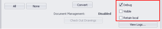
With the Debug option active:
-
The logs provide more detailed information about the conversion process.
-
You can select the Retain Local option, which applies to conversions in both directions. Once the converted drawing is sent to the Cloud, there is no way the CAD user can access that converted file. Therefore, for debugging purposes in both directions, retaining the local copy of the converted drawing is useful. If the drawing import process fails, you can consult the file that was being imported for review and resolving any specific issues.
-
You can select the Visible option to see the actual processes being run. Use this option to monitor the conversion process.
Configuration Step for Drawings with Text that Does Not Reside in the Polyline Boundary
In order to import drawings into Serraview, the insertion point of space text must completely reside inside the polyline boundary it is associated with. The conversion process adjusts the text as necessary to accomplish this, but does require a configuration change.
If you have drawings whose text does not entirely fit within the polyline, you must do the following in Serraview:
- In Serraview, load the Configuration / Setup screen as shown below.
-
Add the following two attributes to the specified node in the DWG Template Schema:
<Plotting UseView="true" UseRegex="true"> - Click the Update button at the bottom of that form.
- Click the Save button on the upper left of that form.
