Eptura for AutoCAD plugin
When you have a floor plan ready for upload, then you can use our AutoCAD plugin to publish the floor plan into Eptura.
Contents
- Prerequisites
- Software Installation and Configuration
- Publishing Floor Plans
- Sign in to Eptura
- Configure Drawing Properties
- Drawing Properties for Floor Plan Shapes
- Drawing Configuration for Floor Plan Markers
- Drawing Configuration for Floor Plan Backgrounds
- Review Spaces
- Publish Floor
- Space Labels
- Manage Space Label Positions
- Publish Space Types
- Settings and Error Logging
- Application Settings
- Applications Errors
Prerequisites
- You have access to Eptura.
- You have access to AutoCAD 2021 or newer on the client machine, where you will publish floor plans.
Software Installation and Configuration
Eptura for AutoCAD - Installation
Your Eptura onboarding partner will provide you with the latest Eptura for AutoCAD installer:
- Eptura for AutoCAD 2024 and earlier
- Eptura for AutoCAD 2025
After you have downloaded the plugin, complete the following:
- Run the downloaded installer and follow the instructions provided by the installation wizard.

During installation, it is recommended to accept the default installation location.
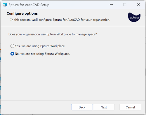
- During installation, you will be prompted for the Installation Type.
- If your Eptura implementation includes Eptura Workplace, select the Yes, we are using Eptura Workplace option.
- If your Eptura implementation does not include Eptura Workplace, select the No, we are not using Eptura Workplace option.
- Click the Next button to "Ready to install Eptura for AutoCAD 2024".
- Click the Install button and the plugin installation begins.
- When the installation is completed, click the Finish button.
Publishing Floor Plans
- Launch AutoCAD.
- Open the drawing with the floor to publish and the Eptura for AutoCAD menu and ribbon displays.

Sign in to Eptura
- From the ribbon, click the Sign In button.
- If it is the first time you have signed in, you will be prompted for your email address.
- Click the OK button.

After providing your email to sign in to Eptura either via SSO or manually.
Sign in with SSO (Single Sign On)
If you sign in with SSO then you will be re-directed to authenticate with your identity provider.
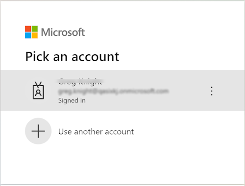
Sign in with Form Authentication (Manually)
Or if you sign in with an email, then you will be redirected to authenticate with Eptura, see Sign in to Eptura - Sign in with Form Authentication (Manually).
After successful sign in, the Eptura for AutoCAD toolbar items will be enabled.

Configure Drawing Properties
Configure the floor plan for publishing with the EpturaProperties command.
- From the ribbon, click the Drawing Properties.
The Drawing Properties contains settings for the Location and Units, and the Drawing Configuration. The Location and Units section contains settings for the Eptura building and floor, as well as the source units of the drawing.

- In Location and Units, enter the Eptura building, floor, and drawing units.
- Click the OK button.
Eptura for AutoCAD automatically detect the correct drawing units, if these are configured properly in the drawing. If the correct drawing units are not automatically detected, it is recommended you set these properly with the AutoCAD UNITS command.

Drawing Properties for Floor Plan Shapes
Drawing Configuration contains settings about the floor plan type and the configuration of floor boundaries, space boundaries, and space identifiers.
Shape-based floor plans require a floor boundary, space boundaries and space identifiers. Floor boundaries, space boundaries, and space identifiers must reside on their own layers. There is no requirement to use Eptura defined layers. Users can place these boundaries on whatever layers they desire and configure the drawing accordingly.
Floor boundaries represent gross areas. A single floor boundary (required) represents the external gross area. An additional floor boundary (optional) may represent the internal gross area. Floor boundaries must reside on their own layer; e.g. A-AREA-FLOOR.
Space boundaries represent space areas and must contain a corresponsing space identifier. Space boundaries must reside on their own layer; e.g. A-AREA-SPACE.
Space identifiers can be implemented using blocks with attributes, or simple text objects. Each space boundary must have one and only one space identifier. Space identifiers must reside on their own layer; e.g. A-AREA-IDEN-NAME.
| Floor Plan Shapes Geometry | Floor Plan Shapes Layers |
|---|---|
 |
 |
Specify the floor and space boundary layers. Specify the source and configuration for space identifiers.

The Drawing Properties settings will be preset if the location and configuration are recognized. Otherwise create a new configuration with the New and Save commands.
Drawing Configuration for Floor Plan Markers
Drawing Configuration contains settings about the floor plan type and the configuration of space identifiers.
Marker-based floor plans require only space identifiers. Marker-based floor plans do not require floor or space boundaries. As such, floor and space areas are not published for marker-based floor plans.
Space identifiers represent the location of the space, and like shape-based floor plans, can be implemented using blocks with attributes, or simple text objects.
| Floor Plan Marker Geometry | Floor Plan Maker Layers |
|---|---|
 |
 |
Specify the source and configuration for space identifiers.

The Drawing Properties settings will be preset if the location and configuration are recognized. Otherwise, create a new configuration with the New and Save commands.
Drawing Configuration for Floor Plan Backgrounds
Drawing Configuration contains settings about the floor plan type.
Background floor plans do not require floor boundaries, space boundaries, or space identifiers. As such, no floor or space data will be published for background floor plans.
Floor plan background with no boundaries or identifiers.
| Floor Plan Background Geometry | Floor Plan Background Layers |
|---|---|
 |
 |
There is no configuration required for floor plan backgrounds.

Review Spaces
After configuring the drawing properties, verify spaces to be published.
From the ribbon, click the Spaces.

The Spaces form provides a space count and total area of the floor, as well as details of each space, which will be published.

Space Errors
If there are spaces in the drawing which have problems of any sort (e.g. missing boundary or identification), the space will be highlighted in red and a warning will be displayed at the bottom of the Spaces form. Space errors must be corrected before publishing.

Publish Floor
From the ribbon, click the Publish button.

If the information in the Publish Floor dialog is correct, proceed with publishing the floor plan.

The user will be notified that the publishing process is in progress.

The user will be notified when the publishing process is complete.

After publishing, the floor plan is available in Eptura. Floor plans can be accessed in Eptura products that support platform floor plans.
Space Labels
Manage Space Label Positions
The position of space labels in the published floor plan is managed in the source drawing. For shape and marker floor plans, labels in the published floor plan will be placed at the location of the labels in the source drawing. For shape-based floor plans, Eptura provides tools to align space identifiers with the geometric center of their space boundaries. Alternatively, users can use native AutoCAD commands and techniques to position labels to their liking.
To use the Eptura Center Space Labels command, the drawing must be configured as a Shapes floor plan.
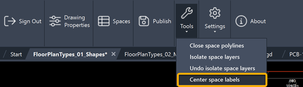
The Center Space Labels command will move space labels to the geometric center of the parent space boundary.
| Before Center Space Labels Command | After Center Space Labels Command |
|---|---|
|
|
Space labels are moved to the geometric center of the parent space boundary
|


Publish Space Types
Space types can be optionally published for shape and marker floor plans. Space types are configured in Drawing Properties > Drawing Configuration, along with boundaries and space identifiers. Space types must reside on their own layer; e.g. A-AREA-IDEN-TYPE.
Space types can be published under the following conditions:
- Space Types must exist in the Space Service. Space Types are configured in the Space Types tool, available from Eptura Home.
- Space Types that don’t exist in the Space Service will be published as default space type Unknown.
- Space Types will only be published the first time a floor plan is published. Once the Space Type is published/established for a space, they must be managed (changed) in Portfolio Manager.
- Space Types will only be published when a floor plan is republished, if the space has the default space type of Unknown in the Space Service.
To publish space types, configure them in Drawing Properties, along with boundaries and space identifiers:

When Space Types are configured, they will be included in the space data displayed in the Spaces command:

Space types can be viewed, along with associated space data, in Eptura Portfolio Manager.
Settings and Error Logging
Application Settings
From the ribbon, click Settings > Application Settings.

Application Settings includes options to control client and server logging.

Application Errors
If errors occur at any point, details can be found in the View Client Log.
From the ribbon, click Settings > View Client Log.
